Home >> Electricity, cathode ray oscilloscope
construction |
Construction
The cathode ray oscilloscope consists of three main elements:
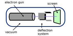
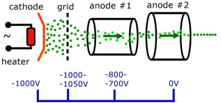
electron gun
Electrons are produced by thermionic emission.
Essentially a cathode(negative electrode) is heated and electrons boil off the surface to be attracted by a series of anodes (positive electrodes).
The anodes accelerate the electrons and collimate them into a narrow beam.
deflection system
The deflection system consists of two pairs of parallel plates called X-plates and Y-plates.
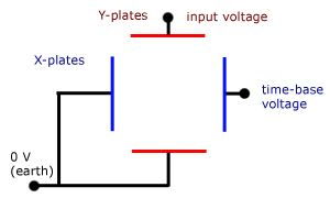
To display a waveform, a repetitive reversing voltage is applied to the X-plates.
This causes the electron beam to be slowly repelled from the left-hand plate and attracted towards the right-hand plate.
On the CRO screen this translates as an illuminated dot moving from left to right.
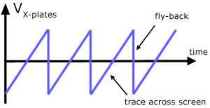
The voltage is then reversed and increased rapidly. The effect is to move the dot very quickly from right to left (fly-back).
The applied voltage is called the time-base. The curve has the general shape of a 'saw-tooth' and is often referred to by this name.
The p.d. applied to the Y-plates is the signal to be examined.
With the p.d. across the X-plates (the time-base) switched off, a sinusoidal signal makes the dot go up and down, executing simple harmonic motion.
With the time-base on, a sine wave is displayed.
display
The display screen is coated on the inside with a very thin layer of a phosphor called cadmium sulphide.
This fluoresces (gives out green light) when electrons impact its surface.
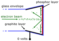
A layer of graphite is painted on the the inside of the vacuum tube close to the fluorescent screen.
As a result of impacting electrons, the screen acquires a negative charge. To reduce this effect, the graphite is electrically connected to 'earth' (zero volts). This allows excess charge to drain away.
Without this feature, the accumulated charge would reduce the numbers of electrons arriving at the screen, reducing brightness.
The graphite layer also catches rebounding electrons that are back scattered from impact with the screen.
Controls
brightness
The brightness of a CRO display is a measure of the numbers of electrons impacting the screen.
The heating element heats the cathode in the 'electron gun' to produce electrons forming a beam current.
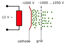
This beam current is controlled by having a grid over the cathode. The p.d. of the grid can then be varied to accelerate electrons through it or repel some back to the cathode.
focus
The electron beam is focussed by passage through several annular anodes.
These 'collimate' the beam into a narrower, faster stream of electrons, producing a smaller, sharper dot on the screen.
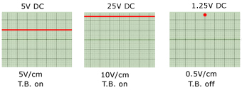
time-base
This controls how fast the dot moves across the screen.
With the time-base switched off, the dot appears static in the centre.
With higher settings the dot appears as a horizontal line.
The control has units of 'time/cm' or 'time/division', with settings in the range 100 ms - 1 μs per cm/division.
sensitivity/gain
This controls the vertical deflection of the dot. It has units of 'volts/cm' or 'volts/division'.
Measurement of alternating voltage
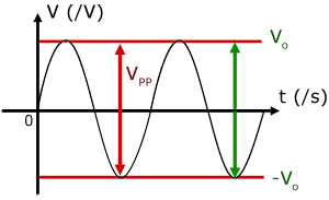
It is important to know the names of vertical measurements on a waveform.
The peak voltage (V0) is the maximum vertical displacement measured from the time-line.
The peak-to-peak voltage (VPP) is the vertical displacement between the minimum and maximum values of voltage.
VPP = 2 V0
Measurement of frequency
Frequency is measured by finding the 'wavelength' of the waveform along the time-line.
In other words to find the period (T) of the wave (the time interval for one complete oscillation).
T = (horizontal dist. on screen in cm) x (time-base setting)
Once T has been measured, the frequency f can then be found. The period T is inversely proportional to frequency f :
![]()
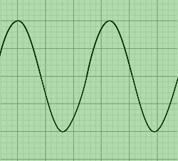
Example: In the example above, measuring from the first crest to the second horizontally, the distance is 3.3 cm.
If the time-base is 2ms/cm (2 x 10⁻³ sec./cm), then the period (T) is:
T = 3.3 x 2 x 10-3 = 6.6 x 10⁻³ secs.
Hence the frequency (f) is:
f = (6.6 x 10⁻³)-1 = 151.5 Hz (1 d.p.)
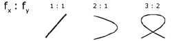
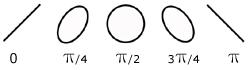
Another way of measuring frequency is by Lissajous figures.
These images are obtained by switching off the time-base and inputting an AC signal into it.
We then have the case where we have two AC signals, one across the X-plates and the other across the Y-plates.
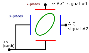
Different ratios of frequency give different images. In this way an unknown frequency can be identified, provided it is in a simple ratio with the first frequency.
Measurement of phase difference
On a double beam oscilloscope the phase difference in cm is be measured along the time-line between similar points on each wave.
To measure the phase difference in radians, the horizontal length of one wave (in cm) must also be known (the period).
Then the phase difference is given by:
![]()
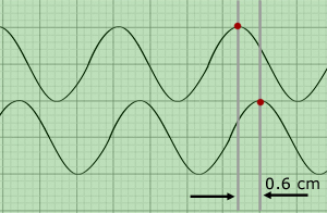
Example: The phase difference is 0.6 cm and the wavelength is 3.1 cm. therefore :
phase difference (φ phi) =( 2 π x 0.6)/3.1 = 1.2 rads.
Besides frequency, Lissajous figures can also be used to identify phase differences.
this week's promoted video
[ About ] [ FAQ ] [ Links ] [ Terms & Conditions ] [ Privacy ] [ Site Map ] [ Contact ]