Home >> Fields, magnetic fields 2
Flemming's LH Rule |
|
Flemming's Left Hand Rule
The rule describes the resulting directional motion of a current carrying conductor(or a moving charged positive particle) from the current and field directions.
The three quantities FIELD, CURRENT AND MOTION are mutually at right angles to each other.
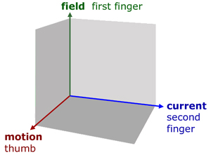
using the left hand, position the first finger, second finger and thumb to form the x,y,z axes. The highlighted letters within the words help you remember the three quantities
First finger - Field direction
seCond finger - Current direction
thuMb - Motion produced
Force on a charged particle in a magnetic field
The force on a charged particle moving in a magnetic field is at right angles to the velocity. This causes the particle to perform circular motion.
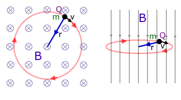
For a velocity at right angles to the field, the magnitude of the force F is simply the product of the magnetic flux density B, the charge Q on the particle and its velocity v.
![]()
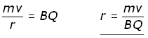
Equating this force with the centripetal force, we obtain the relation :
![]()
Rearranging to make the radius of motion r the subject :
This is quite an important result.
The radius r is :
i) directly proportional to the momentum (mv)
ii) inversley proportional to the flux density B
iii) inversley proportional to the charge Q
Whether a particle orbits clockwise or anticlockwise indicates charge type(+ or -). So with information from orbital radius particles can be identified in nuclear physics experiments.
Now consider a particle moving at velocity v at an angle θ to a magnetic field of flux density B.
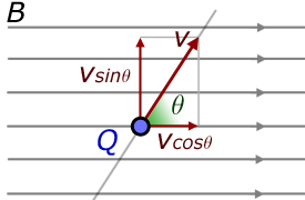
The velocity v is resolved along the field ( vsinθ ) and at right angles to it ( vcosθ ).
This means that the particle performs circular motion with a velocity at right angles to the circle. The result is a corkscrew motion.
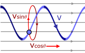
Circular motion velocity is now vsinθ (not v). Therefore the original equation for normal field and velocity is amended to :
![]()
Force on a metal conductor in a magnetic field
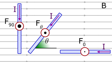
For a metal conductor of length L , carrying a current I , at right angles to a magnetic field of flux density B , the force F upwards on the conductor is simply : (left-hand diagram)
![]()
For a metal conductor at an angle θ to the field, the force upwards on the conductor is : (centre diagram)
![]()
For a metal conductor in-line with the field (right-hand diagram) θ = 0o and sine 0o = 0 . Hence the force F is zero.
The expression ![]() can be derived from first principles.
can be derived from first principles.
Consider a metal conductor of length L with electrons travelling along it with an average drift velocity v.
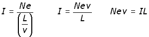
The average time t for an electron to traverse the length L, (using time = distance/velocity) is :
![]()
If Q is the charge transferred along the conductor in time t , then the current I (by definition the charge passes in unit time) is :
![]()
The charge Q is a particular number n of electrons :
![]()
Substituting for Q and t into the expression for current I :
Quoting the equation for a moving particle at an angle to a magnetic field :
![]()
Substituting for Q : (![]() )
)
![]()
rearranging,
![]()
Substituting for Nev from above,
![]()
The Hall Effect
The Hall Effect refers to the potential difference that builds up across opposing faces of a cuboidal shaped material when it is carrying current and placed in a uniform magnetic field.
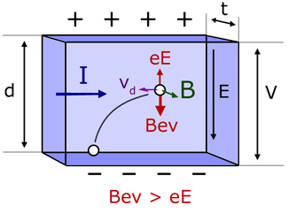
The potential difference V is a consequence of free electrons in the material being deflected by the magnetic field. The electrons move in arcs and build up on the bottom face. Removal of free electrons from the top half of the solid makes the top face positive.
The electric field E produced by the deposited electrons is very weak to start with. As more electrons accumulate, it grows stronger. The resultant force on electrons(Bev - eE) becomes weaker and weaker. Eventually a point is reached when the magnetic and electric forces are equal(Bev = eE) and no more electrons are added.
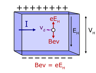
When this happens the potential difference across the top and bottom faces is a maximum (VH). The p.d. is called the Hall Voltage and is a measure of the magnetic field passing through the solid.
An expression for the Hall Voltage can be obtained from a consideration of the forces on an electron, when they are balanced.
The downward magnetic force F is given by :
![]()
The upward electric force is given by :
![]()
For a uniform electric field,
![]()
where d is the thickness of the sample.
Substituting for E into the electric force equation,
![]()
Equating the magnetic force with the electric force :
![]()
cancelling the e's and making VH the subject of the equation,
![]()
Quoting the Drift Velocity equation from the site's Electricity section: electricity/conduction in metals
![]()
Rearranging to make the drift velocity v the subject,
![]()
Now, substituting for v into the equation for VH ,

The cross-sectional area A of the sample between left and right faces is simply the product of the height d and its thicknes t.
![]()
Substituting for A in the new expression for VH ,
![]()
Shuffling around bottom terms to make the equation more memorable :

The Hall voltage is larger in semiconductors than metals. This is because VH is inversely proportional to the number of charge carriers/unit volume n. Values for n are much smaller in semiconductors. So VH is larger.
Typical values of VH for specimens under similar conditions :
metals ~ 10-6 V
semiconductors ~ 10-2 V
A useful application of the Hall Effect is to test whether a material is p or n-type semiconductor.
Note also how Hall Voltage VH is inversely proportional to sample thicknes t. So a thin sample (a small t) will give a large Hall Voltage.
this week's promoted video
[ About ] [ FAQ ] [ Links ] [ Terms & Conditions ] [ Privacy ] [ Site Map ] [ Contact ]