Home >> Fields, electromagnetic induction 1
description |
||
Description of the Phenomenon
A rapidly changing magnetic field induces electric currents to flow in a closed circuit.
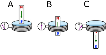
In the diagram above, a bar magnet is dropped vertically through a coil linked to a centre-zero galvanometer.
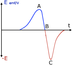
A graph of coil EMF against time shows that:
When the first pole(S) falls through the coil EMF increases to a level then decreases.
When the middle of the magnet falls throught the coil, the EMF is at a minimum. No lines of force are being cut by the coil.
Maximum EMF is obtained when the second pole(N) falls through the coil. This is when the rate of cutting lines of force is highest, because the magnet is falling faster. As a result of the velocity being greater the period of high EMF is shorter.
NB As a result of the field direction being reversed when the poles drop through the coil, the induced current direction is also reversed.
So the EMF is also reversed (EMF is directly proportional to current).
Faraday's Law
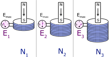
Consider different sized coils when the same magnet is introduced into the body of each coil with the same velocity.
It is found that,
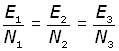
So induced EMF E is directly proportional to number of turns N,
![]()
Now consider just one coil and in turn introduce three magnets. The magnets are of different strengths and are introduced into the coil at the same velocity.
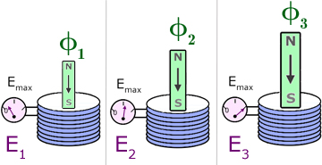
By measuring the maximum EMF and flux for each magnet, it is found that,
So induced EMF E is directly proportional to flux φ,
![]()
Faraday's Law simply states:
The induced EMF in a closed circuit is directly proportional to the flux linkage.
Flux linkage Nφ is the product of flux φ and the number of turns N on a coil.
We have seen that,
![]()
Therefore,
![]()
Lenz's Law
The direction of the induced EMF is such that the induced current opposes the change
producing it.
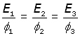
So when a magnetic south pole is moved towards a coil in a circuit, the face of the coil presents a south pole.
The induced current is opposing the change that produced it by trying to prevent the south pole from entering the coil (by repelling it).
Similarly, when a south pole is pulled from a coil in a circuit, the face of the coil presents a north pole.
The induced current is opposing the change that produced it by trying to prevent the south pole from leaving the coil (by attracting it).
NB
| 1.) how the current direction is changed by the magnet direction.
2.) on each coil face, how a line drawn between the ends of arrows(in grey) makes an
'N' and an 'S' , giving the polarity of the coils. |
Neumann's Equation
This combines the proportionalities in Faraday's Law with the direction of the induced current from Lenz's Law.
As a result of the consistency of units used (SI), there is no need for a constant of proportionality.
![]()
The minus sign is from Lenz's law, indicating the opposing nature of induced EMF and rate of flux linkage cutting.
The equation can be amended to include the rate of flux cutting dφ/dt by taking the number of coils N out of the differential.
![]()
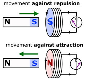
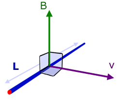
Flemming's Right Hand Rule
The rule describes the resulting directional motion of the induced current for a conductor moving at right angles to the field direction.
The three quantities FIELD, CURRENT AND MOTION are mutually at right angles to each other.
Using the right hand, position the first finger, second finger and thumb to form the x,y,z axes.
The highlighted letters within the words help you remember the three quantities.
| First finger - Field direction
seCond finger - Current direction
thuMb - Motion produced |
EMF Induced in a Metal Rod
For an induced EMF E to be produced across the length L of a metal rod, the magnetic field B, the velocity v and the major axis of the rod must all be mutually at right angles to each other.
The derivation of E = BLv :
Consider a metal rod of length L.
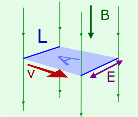
If the rod is travelling at a velocity v at right angles to its length then the area A swept out per second is given by:
![]()
The total flux φ threading through this area per second is the product of the area A and the flux density B.
![]()
Substituting for the area A,
![]()
In this case, since the total flux φ refers to 1 second, we can write :
![]()
where dφ/dt is the rate of flux cutting.
Hence,
![]()
By definition, EMF (E) is equal to the rate of flux cutting,
![]()
Therefore,
![]()
this week's promoted video
[ About ] [ FAQ ] [ Links ] [ Terms & Conditions ] [ Privacy ] [ Site Map ] [ Contact ]