Home >> Electricity, simple circuits
Kirchhoff's Laws |
|||
Kirchhoff's Laws
1st Law - The sum of the currents entering a node/junction equals the sum of the currents leaving.
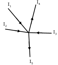
I1 + I2 + I3 = I4 + I5
I1 + I2 + I3 - I4 - I5 = 0
This can also be expressed as the algebraic sum: Σ I = 0
2nd Law - Around any closed loop in a circuit, the algebraic sum of the individual p.d.'s is zero.
This can also be described as:
Around any closed loop in a circuit, the sum of the emf's equals the sum of the p.d.'s across resistive elements.
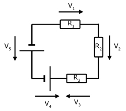
V1 + V2 + V3 - V4 - V5 = 0
The convention is that clockwise p.d.'s are positive.
Simply, emf's cause a rise in pd. Other circuit elements(eg resistors) cause falls in pd. In a closed circuit, the sum of the rises in pd equals the sum of the falls.
Resistors in series
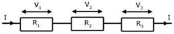
Consider three resistors, R1 R2 R3 with the same current flowing through each.
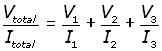
If the p.d. across each one respectively is, V1 V2 V3 . Then the total p.d. Vtotal across the arrangement is:
![]()
By Ohm's law, V=IR, therefore:
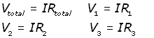
substituting for Vtotal V1 V2 V3 into the equation for p.d.,
![]()
![]()
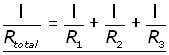
Resistors in parallel
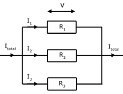
Consider three resistors R1 R2 R3 with the same p.d. (V) across each of them.
Using Kirchhoff's 2nd law, we can write:
![]()
By Ohm's law, V=IR and I=V/R , therefore :
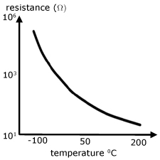
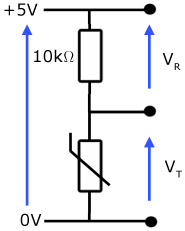
The Thermistor
A thermistor is a bipolar* semiconductor circuit element. It is in effect a temperature dependent resistor.
*contacts can be connected + - or - +
The arrangement below is called a potential divider. The p.d.'s VR and VT are in the ratio of the resistors they appear across.
When the thermistor is hot its resistance is low and of the order of 100's of ohms. In this case, most of the 5V p.d. falls across the 10kΩ resistor.
As the temperature decreases, the resistance of the thermistor increases.
When its resistance reaches 10kΩ the p.d. is shared equallybetween it and the series resistor.
At really cold temperatures the resistance increases to the order of MΩ's, when most of the p.d. falls across it and not the series resistor.
The Light Dependent Resistor (LDR)
Like the thermistor, the LDR is also a bipolar semiconductor circuit element. LDR's are made from high resistance semiconductor material, whose resistance decreases with increasing incident light intensity.
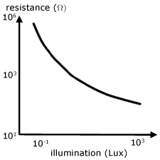
Typically effect of light on a LDR is to reduce its resistance from ~ 106 Ω to ~ 102 Ω.
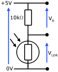
The arrangement below is called a potential divider. The p.d.'s VR and VLDR are in the ratio of the resistors they appear across.
In the dark, the resistance of the LDR is of the order of MΩ's. So most of the 5V p.d. falls across it and not the series resistor.
With more illumination, the resistance of the LDR decreases. When it reaches 10kΩ the p.d. is shared equally with the series resistor.
In bright light, its resistance is of the order of 100's of Ω's. Then, most of the p.d. falls across the series resistor.
Light Emitting Diode (LED)
An LED is essentially a modified junction diode (or p-n diode) so that it gives out light when current flows through it.
Junction diodes are made from two types of semiconductor material, which have been 'doped' to alter their properties.
p-type: rich in charge carriers called 'holes' (missing electrons)
n-type: rich in free electrons
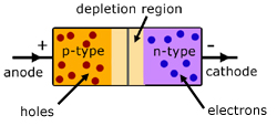
The two types of semiconductor meet in the middle at what is called the p-n junction. Here, with no p.d. applied, the holes from the p-type meet up with the free electrons from the n-type and cancel each other out.
However, when a p.d. is applied, with n-type '-' and p-type '+' (called forward biased), a current flows. This current is made up of free electrons moving across to the '+' terminal and holes moving towards the '-' terminal.
When the polarity is reversed(reverse bias), with n-type made '+' and p-type made '-' , no current flows. So we have a device that only allows current to flow in one direction.
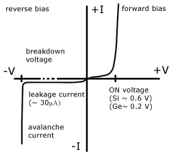
On a V-I graph the top right quadrant shows how a very small forward p.d. causes the diode to conduct. Notice the high current for a small p.d. increase.
The bottom left quadrant shows what happens when the diode is reverse biased ('+' contact connected to '-' supply and vice versa). Notice for increasing p.d. there is a constant 'leakage current' . This is very small, being of the order of micro-amps.
There comes a point when the p.d. is so high that 'breakdown' occurs. A large current passes and the diode is destroyed.
It is essential in LED circuits that the exact p.d. falls across the device. If the p.d. is too high the LED will allow too much current to flow through it. The result will be overheating and failure.
To avoid this, an LED always has a 'limiting resistor' placed in series to limit the current. The level of current designed for is just enough to trigger light from the device.
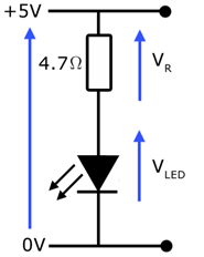
Example: Find the limiting resistor for an LED, where:
i) the max. LED current required is 100mA
ii) the forward LED voltage is 0.65V
iii)the supply p.d. is 5V
If 0.65V falls across the LED, then 4.35V must fall across the limiting resistor.
The current through both the LED and the limiting resistor is 100mA.
Therefore the limiting resistance R is given by R = V/I .
R = 4.35/0.1 = 43.5 Ω
The closest commercial resistor value is 47 Ω
[ About ] [ FAQ ] [ Links ] [ Terms & Conditions ] [ Privacy ] [ Site Map ] [ Contact ]