Home >> Fields, electromagnetic induction 2
self induction |
||
Self Induction
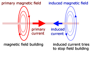
Induced currents only ocur when a magnetic field builds or collapses.
Lenz's law tells us that the induced current is such as to oppose the change producing it.
So the induced current will oppose the primary current when the field is building. Conversely, when the field is collapsing the current will be in the opposite direction to try to prevent the collapse.
In the first instance the induced current field will be in a sense to oppose the primary current building. In the second instance when the field is collapsing, it will be in the same direction to lessen the collapse..
The induced current is produced by a 'back EMF' - an induced voltage proportional to minus the rate of primary current change.
![]()
![]()
where L (the inductance) is the constant of proportionality.
Rearranging to make L the subject of the equation. By making E and dI/dt unity we define the unit of self induction, the henry:

![]()
A coil has a self inductance of 1 henry (H) if the back EMF is 1 volt for a current change of 1 ampere/second.
By equating the EMF from Neumann's equation with self induction EMF a simplified expression linking the two can be formed.
![]()
Integrating between the limits of φ - 0 and I - 0 ,
![]()
![]()
Mutual Induction
Mutual induction concerns a pair of coils. A building current in one coil (the primary) produces a building magnetic field around it. This in turn induces a building current to flow in the other coil. The induced current flow is in such a direction as to produce a magnetic field direction to oppose the primary magnetic field. The magnetic fields are directed towards each other. So their total effect is reduced.
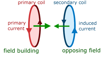
When the primary current direction is reversed its magnetic field direction is also reversed. This has the effect of making current in the secondary reverse direction together with its magnetic field direction. In this case the magnetic fields are in opposing directions.
As with self inductance, the back EMF is proportional to minus the rate of current change. However, in this case the back EMF is in the secondary coil, not and in the primary(as with self induction).
![]()
![]()
Where M (mutual inductance) is the constant of proportionality.
There is another important link between self and mutual inductance. It can be shown, assuming 100% flux linkage that,
![]()
where Lp and Ls are respectively the self inductances of primary and secondary coils.
So the back EMF Es in the secondary coil relates to the rate of current change dIp/dt in the primary.
![]()
The secondary back EMF also relates to the rate of change of flux linkage in the secondary.
![]()
Elimenating Es from these two expressions,
![]()
Integrating between the limits of φs - 0 and Ip - 0 ,
![]()
![]()
Transformer action
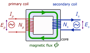
Consider the primary coil. There are two opposing EMF's working here : the applied EMF Ep and the back EMF EB .
If I is the current flowing in the primary and R is its resistance, then from Kirchoff's law for pd's in a circuit:
![]()
Neumann's equation states that EB is given by :
![]()
Substituting for EB in the Kirchoff relation,
![]()
Assuming that the coil resistance R is so low as to be negligible, we have
![]() (i
(i
Both primary and secondary coils have the same flux passing through them. So the rate of flux change dφ/dt will also be the same. It follows that the back EMF Es in the secondary is given by :
![]() (ii
(ii
Dividing equation (ii by equation (i ,
 (iii
(iii
Power in a transformer
Consider a load resistance R connected to the secondary coil.
Quoting the power equation for a circuit,
![]()
where P is power, I current and E EMF.
If we assume that there are no losses (ie that the transformer is 100% efficient) we can write :
power input = power output
If Ip and Is are the currents flowing in the primary and secondary coils, then :
![]()
rearranging,

substituting for Es /Ep from (iii the transformer equation,

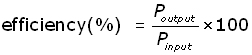
Transformer efficiency
In reality the efficiency of a transformer is not 100%. However efficiency is still high, being in the range 95-99%.
Ways that power is lost within a transformer :
1.) Coil Heating Energy is lost in the coils by resistive heating. The power loss P is given by P = I2R , where R is coil resistance and I the current. This can be reduced by choosing wire thickness according to current.
Between the primary and the secondary, the coil with the smaller number of turns carries the larger current. Therefore this coil is made from thicker wire. Remember the resistance of a wire is inversely proportional to its cross-sectional area. A small cross-sectional area gives a higher resistance. A higher resitance gives a greater power loss.
2.) Eddy Currents Eddy Currents are unwanted induced currents formed in the body of a metal object. Much heating results from high currents induced from low EMFs.
To counteract eddy currents the core is laminated. It is constructed of very thin(approx. 1mm) sheets of soft iron. Each sheet is varnished and insulted from the next.
3.) Hysteresis The core material offers some resistance to the changing strength and direction of the magnetic field(called hysteresis loss). This resistance manifests itself as heat within the core.
The remedy is to make the core of specialist metal (eg permalloy, silicon steel) where hysteresis loss is minimal.
4.) Flux As a result of imperfections in the windings, not all the flux that passes through the primary coil passes through the secondary. This means that not all the energy is transferred between the coils.
general notes:
There are two types of transformer.
A step-up transformer is when Ns > Np and Es > Ep .
For a step-down transformer, the inequality is reversed and Np > Ns and Ep > Es .
The applied EMF in the primary coil must be alternating in nature. A changing magnetic field is a requirement for transformer action.
[ About ] [ FAQ ] [ Links ] [ Terms & Conditions ] [ Privacy ] [ Site Map ] [ Contact ]